What is Shrinkage Cavity?
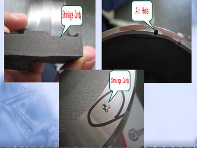
Shrinkage Cavity refers to void defects in shaped metal casting. It is formed during the solidification of the molten metal because of shrinkage.

Shrinkage cavities are usually located in the upper or inner of a casting where the molten metal is last to enter during pouring.
If the shrinkage cavities are not cleaned, wrinkles or holes are formed in the center of the section after the casting is formed. There are often serious loose and oxygen-like accumulations in the vicinity. This will seriously affect the quality of the casting. Cause excessive deformation or fracture of the engineering components.
To prevent the casting from producing defects such as shrinkage Cavity. First of all, we should understand that the dynamic fluid shrinkage of the molten metal in the cavity after the molten metal flows into the cavity during casting
The Reasons of Shrinkage Cavity
1–Casting structure
Because the section of the casting is too thick, it causes poor feeding and shrinkage.The wall thickness of the casting is not uniform. Shrinkage cavity or shrinkage porosity occurs at the hot joint of the wall thickness part.
Because the diameter of the casting hole is too small, the sand core forming the casting hole is heated by the high-temperature molten metal. And it is in a high-temperature state for a long time.
Reduce the solidification rate of the metal on the surface of the casting hole.
At the same time, the sand core provides a channel for gas or atmospheric pressure. This results in shrinkage and looseness in the wall of the hole. The radius of the concave corner of the casting is too small. The heat transfer capacity of the molding sand at the sharp corners is reduced.The solidification rate decreases at the concave corners.
At the same time, due to the strong heating of the molding sand at the sharp corners. The air pressure is too high. The precipitated gas can penetrate into the unsolidified molten metal. Cause the casting to produce gas shrinkage holes.
2–Reasons for smelting
The air content of the liquid metal is too high. It causes precipitation in the form of bubbles during the cooling process of the casting. Prevent adjacent liquid metal from flowing there for feeding. Shrinkage or shrinkage occurs.
When the carbon equal of gray cast iron is too low, the precipitation of eutectic graphite will be reduced when the molten iron is solidified. This reduces the effect of graphitization expansion. Increases solidification shrinkage. It also reduces the liquidity of molten iron.
Thereby reducing the self-compensating capacity of molten iron. Make the casting easy to produce shrinkage cavity or shrinkage porosity.
3. Reasons for process design
(1) The design of the pouring system is unreasonable
When the design of the gating system contradicts the solidification principle of the casting. It may cause shrinkage or porosity in the casting. The main manifestation is improper pouring position. Not conducive to sequential solidification.
The position and size of the inner gate are incorrect.
For gray cast iron and ductile iron, if the inner gate is opened at the thick wall position of the casting. The inner gate size is thicker. After pouring, the inner gate remains in a liquid state for a long time. Under the action of graphitization expansion during the solidification of molten iron. The molten iron will flow back to the sprue through the inner gate. So that the casting produces shrinkage cavity and shrinkage porosity.
(2) Unreasonable design of pouring and riser system
a. The pouring riser design cannot promote the solidification sequence.
The position and size of the pouring riser must be designed according to the different conditions of the casting section. It is necessary to consider which sections will solidify first without pouring risers. Which sections are solidified later? The final solidified part must have a sprue or riser that is still in a liquid state for feeding.
b. The Insufficient number of pouring risers or improper gate design.
The insufficient number of pouring risers is a common cause of shrinkage defects. The feeding distance and range of each gate are limited. The size of the feeding range depends on the thickness of the section, the temperature of the molten metal, and the metal composition. The thinner section will condense faster and will cut off the feeding channel. Improper gate design. If the cross-section of the gate is too small, it will cause premature condensation. Now, even though there is a lot of molten metal in the riser, it cannot be fed into the casting.
c. The riser is too small.
The too-small size riser is also a common mistake. In general, the cross-sectional size of the riser should be larger than the cross-sectional size of the casting that needs to be fed.
Another mistake is to increase the feeding effect by increasing the height of the small diameter riser. This approach is often unsatisfactory.
Because the diameter of the riser is small, the molten metal in the riser is easy to condense.
Even increasing the height of the riser will not help.
The ideal shape of the riser should be spherical. Because its heat dissipation area is the smallest. In some cases, chilling thick sections is an effective and workable method.
d. Improper ratio of riser neck and casting size.
The size of the riser neck is very important for feeding efficiency.If the size of the riser neck section is too small, the feeding effect will be affected.Make sure that the molten metal is unblocked in the neck of the riser.
e. The inner gate is too large.
Shrinkage holes at or above the inlet of the ingate are usually caused by the ingate being too large.
Because the gate entrance is surrounded by hot sand. If its size is too large. The molten metal at the entrance will remain until the end before it solidifies. Now, there is no other metal solution that can feed it.So, shrinkage holes will occur at the entrance of the gate. The correct pouring riser design should first solidify the casting. Afterward, the inner gate and riser neck are solidified. Finally, the riser is solidified. If this solidification sequence is destroyed, shrinkage defects will occur.
(2) Reasons for molding sand and core sand
The refractoriness and high-temperature strength of molding sand (core sand) are too low. The thermal deformation is too large.
Under the action of the static pressure of the molten metal or the expansion force of graphitization, the mold wall or the core wall will move.
Increase the amount of feeding actually required for the casting or new hot spots appear in the expansion part.
It will cause shrinkage cavity and shrinkage porosity in the casting. This phenomenon is very sensitive to large and medium-sized castings.
(3) Reasons for pouring
The pouring temperature is too high. The liquid shrinkage of the liquid metal increases.
When it is too low, it will reduce the feeding capacity of the riser.
Especially when the bottom injection gating system is used. Castings often produce shrinkage cavities and shrinkage porosity in the lower part.
When the riser is not filled or the large and medium-sized castings are not supplemented with molten metal on the riser. This will reduce the feeding capacity of the riser. It will cause shrinkage or shrinkage of the casting.
Shrinkage Cavity classification
Shrinkage Cavity can be divided into open shrinkage and Invisible shrinkage
1- Open Shrinkage Cavity
After the casting, the casting is solidified and cooled, and the riser is peeled off to remove the riser, and the hole is exposed at the raised part of the casting or the flat riser portion is known as the open shrinking hole.
2 – Invisible Shrinkage Cavity
The hole of the shrink hole is a hole hidden in the hot section of the casting. The naked eye is not noticeable. It must be mechanically machined or when the scrap iron is broken.
Shrinkage characteristics
1– Open shrinkage characteristics
To prevent the shrinkage or exhaust of the castings during the molding. It is common to provide a cylindrical riser, a bottle-type riser, and a crimping riser in the plane of the casting or the raised part of the casting. Due to insufficient iron in the riser, when the riser is knocked out, the surface of the casting is exposed. That is open shrinkage holes.
The edges of the holes are flat or have rounded corners and sharp corners. The inner wall of the hole is dark gray or shiny with oxidized color. The holes are irregular in shape and resemble a funnel. Sometimes there are small holes in the hole, which are more than 20mm deep.
2– Invisible shrinkage characteristics
The Invisible shrinkage, also known as the inner shrinkage hole, is hidden in the hot section of the wall thickness of the casting. A single hole appears and is invisible to the naked eye. It can only be found during machining or after machining.
The shape of the hole is similar to an irregular shape such as a pear shape, an elliptical shape, a circular shape, and a long flat shape. The inner wall of the hole is rough and has a dark gray or lustrous oxidized color.
How to prevent Shrinkage Cavity :
1–Choose the right alloy composition
When conditions permit, try to select alloy composition with a narrow crystallization temperature. For example, gray cast iron and nodular cast iron, the chemical composition is selected near the eutectic point. This can help reduce or drop shrinkage and porosity of the casting.
2–Control the smelting process Effectively
Use liquid alloys with good metallurgical properties. The rigidity of the casting varies with the compaction rate of the molding and the type of casting. The casting selection should be reasonable according to the technical requirements of the casting and the actual production situation. If possible, increase the rigidity of the casting. Improve the heat dissipation conditions of the casting.
3–Adopt a reasonable casting process
Adopt the lead-in position of the pouring system and the pouring process. Comprehensive use of risers, cold iron, and subsidies. And adding heating agent and heat-insulating agent on the sprue cup and the riser.
4–Adopt a reasonable smelting process
Reduce gases and oxides in metals. Improve its liquidity and supply capacity.
5– Improve casting structure
Improve the casting structure. Strive for uniform wall thickness. Reducing the hot spots or changing the wall thickness of the casting is conducive to sequential solidification.

